Module - 1: Introduction to Microwaves
On completion of this module, you will be able to:
- Microwave frequency band spectrum
- Learn different types of microwave tubes
- Explain Klystron tubes and its working
- Explain Reflex Klystron tubes and its working
- Explain Travelling Wave tubes and its working
- Explain Magnetron and its working
Introduction
- Radio frequency : It is any of the electromagnetic wave frequency that lie in the range extending from 3 KHz to 300 GHz are used for communications or radar signals.
- Microwave are electromagnetic(EM) waves whose frequency in the ranging from about 300 MHz to 300 GHz. Microwave Engineering deals with systems operating at these frequencies.
- The word Microwave means very short wave, which is the shortest wavelength region of the radio spectrum and a part of the electromagnetic spectrum.
- Microwave are so called since they are defined in terms of their wavelength. In other words micro means very small, hence microwaves have very small wavelength i.e. in the range of 1 mm to 100 cm .
- It is used to design of communication/navigational systems in the Microwave frequency range.
- At Microwave frequency, the conventional electronic circuits radiate more and more power from the circuit.
- So new circuit techniques are required for handling signals in this frequency range.
- Increasing frequency to microwave range is the fact that, the propogation time for signals from one point to another point in a circuit become comparable with the time period of the signal.
- Thus conventional Low frequency circuit analysis techniques based on KVL and KCl concepts are inapplicable to microwave circuits.
- So it becomes necessary to carryout analysis of microwave circuits in terms of electric and magnetic fields.

Microwave frequency band in radio spectrum
- The entire Electromagnetic spectrum is broadly classified into two regions namely -
1. Radio Spectrum - 0 to 300 GHz ( radio frequency spectrum: 300 KHz to 300 MHz and Microwave frequency spectrum : 300 MHz to 300 GHz)
2. Optical Spectrum - 300 GHz to infinity.
| Designation |
Frequency Range |
| L Band |
1 to 2 GHz |
| S Band |
2 to 4 GHz |
| C Band |
4 to 8 GHz |
| X Band |
8 to 12 GHz |
| Ku Band |
12 to 18 GHz |
| K Band |
18 to 26 GHz |
| Ka Band |
26 to 40 GHz |
| Q Band |
30 to 50 GHz |
| U Band |
40 to 60 GHz |
History of Microwave
- Microwaves was first generated by Henrich Hertz in 1868 at 66 cm wavelength (454.5 MHZ).
- Millimeter wave signal was first generated by sir J.C. Bose in 1895 at 5 mm wavelength(60 GHz).
- It was only in the 1940's at the World War II that microwave theory received substatntial interest that led to radar development.
- Communication systems using microwave technology began to develop soon after the birth of radar.The advantages offered by microwave systems such as wide bandwidth and line of sight propagation provides continious development of low cost microwave components.
Advantages of Microwaves
- Large Bandwidth : The Bandwidth of Microwave(1 GHz to 300 GHz) is larger than the common low frequency radio waves.
- Thus due to large bandwidth more information can be transmitted using Microwaves.
- This band can be used for TV, Radio, Radar and other applications
- Improved Directivity- As frequency increases, directivity increases and beam width decreases.
- Less fading effects – at microwave frequencies these are very less fading effects at the medium.
- Very low power is required to use microwave.
- Easily propagates through ionised layers-most suited for satellite communication..
- Popagation delay is negligible or minimum.
Disadvantages of Microwaves
- Measurement at microwave frequencies are difficult.
- At microwave frequencies, circuit design is complex.
- Line of sight propagation limits the use of microwaves.
Applications
- Telecommunication
- Radar
- Commercial and industrial Applications
- Biomedical Applications
- Electronic warfare
- Microwave oven
- Remote Sensing
- Wireless Data Network
Relationship between frequency and wavelength
- The equation which shows the relationship between frequency and wavelength is
f = c / λ
where, f = frequency
c = speed of light = 3*108 m/s
λ = wavelength
- From the above eqation
f ∝ 1 / λ
- Therefore, the higher the frequency, the shorter the wavelength.
Coaxial Line
- Coaxial cables are the most common basic transmission lines. They are used to transmit electrical energy or signals from one location to another: to connect a source to a load, such as a transmitter to an antenna.
- A coaxial cable consists of two conductors separated by a dielectric material.
- The center conductor and the outer conductor are configured in such a way that they form concentric cylinders with a common axis. Hence the term and name co-axial is used.
- A baseband coaxial cable transmits a single signal at a time at very high speed. A broadband coaxial cable can transmit many signals simultaneous using different frequencies.

Waveguides
- A hollow metallic tube of uniform cross section for transmitting electromagnetic waves by successive reflections from the inner walls of the tube is called waveguide.
- TWo wire line, coaxial line, strip line, microstrip and metal waveguides are often used in practice.

- It is a special category of transmission line that is used to guide (direct) the waves (radiation) along the length of the tube. It acts as the medium to transfer or transmit power from point to point.
- Waveguides are used principally at frequencies in the microwave range. In waveguide the electric and magnetic fields are confined the space with in the guides.
- Thus no power is lost through radiation and even the dielectric loss is negligible since the guides are normally air-filled. However there is some power loss as heat in the walls of the guide but the loss is very small.
- Waveguide are two types :
1. Rectangular Waveguide
2. Circular Waveguide

- Rectangular Waveguide: This is the most commonly used form of waveguide and has a rectangular cross section. The dimensions of the cross section sides determine the properties including the cut-off frequency.
- Circular Waveguide: This is less common than rectangular waveguide. They have many similarities in their basic approach, although signals often use a different mode of propagation. The diameter is important as this determines the operating range.
Rectangular Waveguide

- The m and n represent the mode of propagation and indicates the number of variations of the field in the X and Y directions.
- Note that for the TM mode, if n or m is zero, all fields are zero.
- Evanescent means no propagation everything is attenuated.
- The cutoff frequency is the frequency below which attenuation occurs and above which propagation takes place.
- Dominant Mode: the dominant mode is the mode with lowest cutoff frequency. It’s always TE 10. The order of the next modes change depending on the dimensions of the guide.
Maxwell's Equations
- Maxwell's Equations are a set of 4 complicated equations that describe the world of electromagnetic. These equations describe how electric and magnetic fields propagate, interact and how they are influenced by objects.
- Maxwell’s four equations that, together form a complete description of the production and interrelation of electric and magnetic fields.


Maxwell first equation
- Maxwell first equation is based on the Gauss law of electrostatic which states that “when a closed surface integral of electric flux density is always equal to charge enclosed over that surface”
- Over a closed surface the product of electric flux density vector and surface integral is equal to the charge enclosed.
- Mathematically Gauss law can be expressed as,


Maxwell Second equation
- Maxwell second equation is based on Gauss law on magnetostatics. it states that “closed surface integral of magnetic flux density is always equal to total scalar magnetic flux enclosed within that surface of any shape or size lying in any medium.”
- Mathematically it is expressed as –


Maxwell Third equation
- Statement: Time varying magnetic field will always produce an electric field .
- Maxwell’s 3rd equation is derived from Faraday’s laws of Electromagnetic Induction.
- It states that “Whenever there are n-turns of conducting coil in a closed path which is placed in a time-varying magnetic field, an alternating electromotive force gets induced in each and every coil.”
- This is given by Lenz’s law. Which states that “An induced electromotive force always opposes the time-varying magnetic flux.”

Maxwell Fourth equation
- It is based on Ampere’s circuit law. Ampere’s circuit law states that -
- “The closed line integral of magnetic field vector is always equal to the total amount of scalar electric field enclosed within the path of any shape” which means the current flowing along the wire(which is a scalar quantity) is equal to the magnetic field vector (which is a vector quantity)

Modes of EM Wave Propogation
- Transverse Electromagnetic(TEM) Wave: Here both electric and magnetic field is purely transverse to the direction of propagation (i.e.) Ez = 0 and Hz = 0

- Transverse Magnetic(TM) Wave: Here only the electric field is purely transverse to the direction of propagation and the magnetic field is not purely transverse. (i.e.) Ez = 0 and Hz ≠ 0.
TE mode is also represented as TMmn. Where m = number of half sinusoidal cycle variation along X-axiz and n = number of half sinusoidal cycle variation along Y-axiz

- Transverse Magnetic(TM) Wave: Here only the magnetic field is purely transverse to the direction of propagation and the electric field is not purely transverse. (i.e.) Ez ≠ 0 and Hz = 0 .
TM mode is also represented as TMmn. Where m = number of half sinusoidal cycle variation along X-axiz and n = number of half sinusoidal cycle variation along Y-axiz

- Hybrid wave: Here neither electric nor magnetic field is purely transverse to the direction of propagation (i.e.) Ez ≠ 0 and Hz ≠ 0

- Magnetic flux lines appear as continuous loops and electric flux lines appear with beginning and end points.
Structure of Ractangular Waveguide
- Any structure that can guide electromagnetic waves is called waveguide. it is a enclosed conductor filled with an air medium. The side walls have very high conductivity and acts as mirrors that prevent propagation in the transverse direction.
- A rectangular wave guide is a hollow metallic pipe with rectangular cross section.
- A rectangular wave guide support TE and TM mode but not TEM mode.
- Rectangular wave guide usually has a cross section with an aspect ration 1:2 the width being about twice the height.
Condition for Wave Propagation:
- The electromagnetic waves to be transmitted along a confined path are called guided electromagnetic waves, and the systems to transmit the guided electromagnetic waves are called the wave guiding systems.
- For a wave to propagate through the waveguide, it needs to satisfy Maxwell’s equation and waveguide boundary conditions.
- The necessary condition for the wave propagation is cutoff wavelength ( λc ) should be greater than the operating wavelength ( λ0 ) and cutoff frequency ( fc ) should be less than the operating frequency ( f0 ).
λc > λ0
fc < f0
Cut-off Frequency and Cut-off Wave Length :
- Cut-off Wavelength: It is the maximum signal wavelength of the transmitted signal that can be propagated within the waveguide without any attenuation.
- This means up to cut-off wavelength, a microwave signal can be easily transmitted through the waveguide. It is denoted by λc .
fc = (c ⁄ 2). √((m ⁄ a)2 + (n ⁄ b)2)
fcTE10 = c ⁄ 2a
λc = 2ab ⁄ √(m2b2 + n2a2)
λcTE10 = 2a
Intrinsic Wave Impedance of Rectangular Waveguide :
- Wave Impedance: It is also known as the characteristic impedance. It is defined as the ratio of the transverse electric field to the transverse magnetic field during wave propagation at any point inside the waveguide. It is denoted by Zg.
ηTE = 120 π ⁄ (√ 1 - (fc ⁄ f)2) = 120 π ⁄ Cosθ
ηTM = 120 π × (√ 1 - (fc ⁄ f)2) = 120 π × Cosθ
Phase Velocity and Group Velocity :
- Group Velocity: Group velocity is the velocity with which wave propagates inside the waveguide.
- If the transmitted carrier is modulated, then the velocity of the modulation envelope is somewhat less as compared to the carrier signal.
- This velocity of the envelope is termed as group velocity. It is represented by Vg.
- Phase Velocity: It is the velocity with which the transmitted wave changes its phase during propagation. Or we can say it is basically the velocity of a particular phase of the propagating wave. It is denoted by Vp.
V p = c ⁄ (√ 1 - (fc ⁄ f)2) = c ⁄ (√ 1 - (λ0 ⁄ λc)2
V g = c × (√ 1 - (fc ⁄ f)2) = c × (√ 1 - (λ0 ⁄ λc)2
V p.V g = C 2
Guided Wave length :
- It is defined as the distance travelled by the wave in order to undergo a phase shift of 2 π radians. It is related to phase constant by the relation λg = 2 π ⁄ β . Mathematically it is given by,
λg = λ0 ⁄ (√ 1-(λ0/λc)2)
Microwave Network Analysis
- Microwave network analysis is concerned with measuring accurately the incident, reflected and transmitted signals associated with a linear component in a transmission line environment.
- Wireless Data Network
S-parameters (Scattering Matrix )
- At “low” frequencies, we can completely characterize a linear device or network using an impedance matrix, which relates the currents and voltages at each device terminal to the currents and voltages at all other terminals.
- But, at microwave frequencies, it is very difficult to measure the total currents and voltages in a direct manner. Instead, we can measure the magnitude and phase of each of the two transmission line waves V +(z) and V -(z).
- In other words, we can determine the relationship between the incident and reflected wave at each device terminal to the incident and reflected waves at all other terminals.
- So the quantities that may be measured easily are the reflection coefficient and transmission coefficient and this forms the basis of scattering matrix formulation.
- Scattering parameter is also called S-parameter and it is suitable for microwave circuit analysis. It is a network parameter based on the incident and the reflected wave relations.
- It describes the input-output relationships between ports in an electrical system. Specifically at high frequency it becomes essential to describe a given network in terms of waves rather than voltage or current. Thus in S-parameters we use power waves.
- It completely describes the behavior of a linear, multi-port device at a given frequency ω and a given line impedance V z = 0.
- It describe the response of an N-port network to signal(s) incident to any or all of the ports.
- The first number in the subscript refers to the responding port, while the second number refers to the incident port.
- Thus S21 means the response at port 2 due to a signal at port 1.
- Let us consider a two port network for which s-parameters can be defined as :
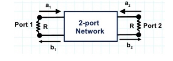
b1 = S11 a1 + s12 a2
b2 = S21 a1 + s22 a2
[b] = [s] [a]
- In the above equation
a1 and b1 represents the incident and reflected waves at port 1.
a2 and b2 represents the incident and reflected waves at port 2.
S11 and s22 represents the input and output port voltage reflection co-efficient.
S12 and s21 represents the reverse and forward voltage gain.
- This concept can further be used to determine s-parameters of a multiport network and it is also used to determine Gain, Return loss, VSWR and Insertion loss.
- The relationship between the scattering matrix and input/output power at different ports can be obtained for N port microwave junction as shown below :

- an is the amplitude of voltage wave incident on port n, while bn is the amplitude of the reflected voltage wave from port n
- If the ports are not properly matched with the junction, there will be reflection from junction back towards the ports
- The scattering matrix is defined in relation to these incident and reflected voltage waves as

Properties of S matrix
- S matrix is always a square matrix of order n x n.
- Under perfect match condition the diagonal elements of S matrix are zero.
- S matrix is always symmetric. ie, Sij = Sji
- S matrix is an unitary matrix. [S][S]* = I. where, I is an identity matrix.
- The sum of product of each term of any row or column multiplied by complex conjugate of corresponding term of another row or column is zero.

- Since S matrix is symmetric [S]T = [S]